Python Script Interface
Script Invocation
HybMesh script is a normal python file which supports all capabilities of python language and can be invoked using both HybMesh standalone application and Python 2.7 interpreter. The latter demands HybMesh be installed as a python module (see Installation).
To invoke a script from python interpreter use a command (if python refers to python2.7)
> python yourscript.py
For standalone Console Application in Windows type
> c:\path\to\bin\hybmesh.exe -sx yourscript.py
In Linux the default application install path /usr/local/bin should present in your system paths, so there is no need to type full path to executable.
> hybmesh -sx yourscript.py
HybMesh functionality is scattered across different modules of
hybmeshpack package. However all imports essential for scripting
are gathered in hybmeshpack.hmscripts.__init__,
so the HybMesh script file should start with respective import line.
Below is a helloworld example which creates a 2x2 grid and reports its structure.
from hybmeshpack import hmscript as hm

g = hm.add_unf_rect_grid([0, 0], [1, 1], 2, 2)
print hm.info_grid(g)
Design
All hybmesh operable geometrical objects
are represented by their internal unique string
identifiers. To get the full list of all registered identifiers
use 'registered_*' functions.
If an identifier leaves current scope
it doesn’t lead to disposing of respective object.
You should use remove_geom() function to explicitly
remove an object. Use remove_all_but() to
clean the garbage and leave only those objects
which are actually needed.
To get full information about object geometry
(vertices coordinates and index based connectivity tables) use
'tab_*' set of functions.
For performance reasons these functions return ctypes plain 1D arrays.
Use ordinary [i] notation to access entries of these arrays
or convert it to python list by pylist = ctypes_array[:] line.
Boundary (zone) types are defined by non-negative integers.
Default zone type (equals 0) is used if it was not explicitly defined.
You could use add_boundary_type()
function to link this integer to a string which will be
used in object export procedures.
Exception Handling
All hybmesh function may throw two types of exceptions:
-
exception
hybmeshpack.hmscript.ExecError(funname, msg)¶ Raised if hmscript function fails
-
exception
hybmeshpack.hmscript.InvalidArgument(msg='')¶ Raised when user passes invalid argument to a hmscript function
Before execution of any hybmesh function a quick
input data check is performed. It examines
argument types, ranges and consistency.
If it fails then InvalidArgument() is raised.
If output verbosity level is not set to zero, then
detailed information regarding this error including
unity based index of invalid argument, its actual value and program expectations
will be flushed to console.
If program fails during function execution
then ExecError() will be raised.
Information about function arguments and traceback
will be printed to console.
Both exceptions could be safely caught and handled.
List of Functions
General routines
Contour operations
2D grid operations
Surface operations
info_surface() |
tab_surf3() |
grid3_bnd_to_surface() |
domain_volume() |
3D grid operations
info_grid3d() |
tab_grid3() |
extrude_grid() |
revolve_grid() |
tetrahedral_fill() |
merge_grids3() |
Export
General Procedures
-
hybmeshpack.hmscript.check_compatibility(vers, policy=1)¶ Checks version compatibility. Notifies if current version of hymbesh is not fully compatible with input version.
Parameters: - vers (str) – version in
"0.1.2"format - policy (int) –
if versions are incompatible then:
- 0 - do nothing (return False)
- 1 - report warning to cout
- 2 - raise ExecError
Returns: False if versions are incompatible, True otherwise.
- vers (str) – version in
-
hybmeshpack.hmscript.registered_contours()¶ Returns list of all contour identifiers
-
hybmeshpack.hmscript.registered_grids()¶ Returns list of all 2d grid identifiers
-
hybmeshpack.hmscript.registered_surfaces()¶ Returns list of all surface identifiers
-
hybmeshpack.hmscript.registered_grids3d()¶ Returns list of all 3d grid identifiers
-
hybmeshpack.hmscript.registered_btypes()¶ Returns list of all boundary types as list of (index, name) tuples
-
hybmeshpack.hmscript.remove_all()¶ Completely removes all geometry objects and boundary types
Returns: None
-
hybmeshpack.hmscript.remove_all_but(objs)¶ Removes all geometry objects except for listed ones
Parameters: objs – identifier or list of identifiers of objects which should NOT be removed Returns: None
-
hybmeshpack.hmscript.copy_geom(objs)¶ Creates deep copies of geometry objects
Parameters: objs – identifier or list of identifiers of objects to copy Returns: list of identifiers of copied objects in oder prescribed by input list
-
hybmeshpack.hmscript.move_geom(objs, dx, dy, dz=0.0)¶ Moves a list of objects
Parameters: - objs – identifier or list of identifiers of moving objects
- dx (float) –
- dy (float) –
- dz (float) – shifts in x, y and z direction. Z moves take place only for 3d objects
Returns: None
-
hybmeshpack.hmscript.rotate_geom(objs, angle, pc=[0.0, 0.0])¶ Rotates group of 2d objects
Parameters: - objs – identifier or list of identifiers of rotating 2d objects
- angle (float) – degree of rotation. Positive angle corresponds to counterclockwise rotation
- pc (list-of-float) – center of rotation
Returns: None
-
hybmeshpack.hmscript.scale_geom(objs, xpc=100.0, ypc=100.0, zpc=100.0, refp=[0.0, 0.0, 0.0])¶ Scales objects
Parameters: - objs – identifier or list of identifiers of scaling objects
- xpc (float) –
- ypc (float) –
- zpc (float) – percentages of scaling in x, y and z directions
- refp (list-of-float) – reference point as
[x, y, z]which stays fixed after transformation
Returns: None
if objs contains only 2d objects zpc is ignored and could be ommitted, refp could by given as
[x, y].
-
hybmeshpack.hmscript.reflect_geom(objs, pnt1, pnt2)¶ Makes a reflection of 2d geometry objects over a given line
Parameters: - objs – identifier or list of identifiers of 2d objects to reflect
- pnt1 (list-of-float) –
- pnt2 (list-of-float) – points in [x, y] format which define a line to reflect over
Returns: None
-
hybmeshpack.hmscript.remove_geom(objs)¶ Completely removes object or list of objects
Parameters: objs – identifier or list of identifiers of removing objects Returns: None
-
hybmeshpack.hmscript.add_boundary_type(index, name='boundary1')¶ Register boundary type name.
Parameters: - index (int) – index of boundary (>0)
- name (str) – user defined name of the boundary
Returns: integer boundary identifier
If boundary with
indexalready exists it will be overwritten. Name of the boundary should be unique, if name already exists it will be changed automatically.
-
hybmeshpack.hmscript.set_boundary_type(obj, btps=None, bfun=None, bdict=None)¶ Mark geometrical object with boundary types.
Parameters: - obj – geometric object identifier
- btps – single identifier for the whole object or list of identifiers for each boundary segment.
- bfun – function which returns boundary type taking segment coordinates and old boundary type as arguments.
- bdict – {btype: [list-of-segment indicies]} dictionary which maps boundary type with object segments indicies
Only one of btps, bfun, bdict arguments should be defined.
bfun signature is:
(x0, y0, x1, y1, bt) -> btypefor 2D objects, where x0, y0, x1, y1 are edge end point coordinates, bt - old boundary type(xc, yc, zc, bt) -> btypefor 3D objects, where xc, yc, zc - approximate face center coordinates, bt - old boundary type
If obj is a grid then only boundary segments will be passed to bfun function and btps list entries will be associated with boundary segments only. However bdict entries should contain global edge or face indicies.
Example:
# mark b1, b2 as globals so binfo function can find them
global b1, b2
# register boundary types
b1 = hmscript.add_boundary_type(1, "vertical")
b2 = hmscript.add_boundary_type(2, "horizontal")
# create rectangular contours
cont1 = hmscript.add_rect_contour([0, 0], [1, 1])
# mark contour using `btps`
hmscript.set_boundary_type(cont1, btps=[b2, b1, b2, b1])
# same effect using `bfun`
cont2 = hmscript.add_rect_contour([0, 0], [1, 1])
def binfo(x0, y0, x1, y1, bold):
    return b1 if x0 == x1 else b2
hmscript.set_boundary_type(cont2, bfun=binfo)
-
hybmeshpack.hmscript.partition_segment(start, end, hstart, hend, hinternal=[])¶ Makes a partition of numeric segment by given recommended step sizes at different locations.
Parameters: - start (float) –
- end (float) – start and end points of numeric segment.
- hstart (float) –
- hend (float) – recommended step at the beginning and at the end of numeric segments
- hinternal (list-of-floats) – possible internal recommended steps given as [segment value0, step0, segment value1, step1, ...]
Returns: increasing float list representing partitioned segment [start, ..(internal steps).., end]
This is a helper function which runs iterative procedure to adopt partition of the segment to user defined step size recommendations. It could be used for example to explicitly define partition in
add_unf_rect_grid(),add_unf_circ_grid()with given custom_* options or vertical partition of boundary grid inbuild_boundary_grid().- Example:
Shows division of [1, 2] segment from approximately 0.1 step size at the beginning to approximately 0.5 step size at the end
print hm.partition_segment(1, 2, 0.1, 0.5)
>>> [1.0, 1.1238348, 1.309012, 1.585923, 2.0]
Shows division of [1, 2] segment with approximate 0.1 step sizes at its end points and 0.4 step size at the center.
print hm.partition_segment(1, 2, 0.1, 0.1, [1.5, 0.4])
>>> [1.0, 1.1082238, 1.3278488, 1.672151, 1.891776, 2.0]
Contour Operations
-
hybmeshpack.hmscript.info_contour(cid)¶ Get contour structure information
Parameters: cid – contour or grid identifier Returns: dictionary representing contour length, total number of nodes, edges, number of edges in each subcontour and number of edges of each boundary type: {'Nnodes': int, 'Nedges': int, 'subcont': [list-of-int], # edges number in each subcontour 'btypes': {btype(int): int} # boundary type: number of edges 'length': float }
-
hybmeshpack.hmscript.tab_cont2(obj, what)¶ Returns plain table for the given contour.
Parameters: - obj (str) – contour identifier
- what (str) – table name
Returns: plain ctypes array representing requested table.
Possible what values are:
'vert'- vertex coordinates table,'edge_vert'- edge-vertex connectivity: indices of first and last vertices for each edge,'bt'- boundary features of each edge.
-
hybmeshpack.hmscript.domain_area(cid)¶ Calculates area of the domain bounded by the contour
Parameters: cid – grid or contour identifier Returns: positive float or zero for open contours
-
hybmeshpack.hmscript.get_point(obj, ind=None, vclosest=None, eclosest=None, cclosest=None, only_contour=True)¶ Returns object point
Parameters: - obj – grid or contour identifier
- ind (int) – index of point
- vclosest –
- eclosest –
- cclosest – point as [x, y] list
- only_contour (bool) – If that is true then if objs is a grid then respective grid contour will be used
Returns: point as [x, y] list
Only one of ind, vclosest, eclosest, cclosest arguments should be defined.
If ind is defined then returns point at given index.
If vvlosest point is defined then returns object vertex closest to this point.
If eclosest point is defined then returns point owned by an object edge closest to input point.
If cclosest point is defined then returns non straight line object contour vertex closest to input point.
-
hybmeshpack.hmscript.pick_contour(pnt, contlist=[])¶ Returns contour closest to given point
Parameters: - pnt – point as [x, y] list
- contlist – list of contour identifier to choose from
Returns: closest contour identifier
If contlist is empty then looks over all registered contours. This procedure does not take 2d grid contours into account.
-
hybmeshpack.hmscript.create_contour(pnts, bnds=0)¶ Create singly connected contour from sequence of points.
Parameters: - pnts (list-of-list-of-floats) – sequence of points. If coordinates of first and last points are equal then contour is considered closed.
- bnds (single-or-list-of-boundary-identifiers) – boundary type for each contour segment or single identifier for the whole contour.
Returns: contour identifier
- Example:
>>> hmscript.create_contour([[0, 0], [1, 0], [1, 1], [0, 0]],
                           [b1, b2, b3])
-
hybmeshpack.hmscript.create_spline_contour(pnts, bnds=0, nedges=100)¶ Creates singly connected contour as a parametric cubic spline.
Parameters: - pnts (list-of-list-of-floats) – sequence of points. If coordinates of first and last points are equal then resulting contour will be closed.
- bnds (single-or-list-of-boundary-identifiers) – boundary type for each contour segment bounded by pnts or single identifier for the whole contour.
- nedges (int) – number of line segments of resulting contour. Should be equal or greater than the number of sections defined by pnts.
Returns: contour identifier
-
hybmeshpack.hmscript.add_rect_contour(p0, p1, bnd=0)¶ Adds four point closed rectangular contour.
Parameters: - p0 (list-of-floats) –
- p1 (list-of-floats) – bottom left and top right coordinates of the contour
- bnd – single or list of 4 boundary identifiers (bottom, right, top, left) for contour segments. With the default value no boundary types will be set.
Returns: Contour identifier
-
hybmeshpack.hmscript.add_circ_contour(p0, rad, n_arc, bnd=0)¶ Adds circle contour from given center and radius.
Parameters: - p0 (list-of-floats) – circle center in [x, y] format
- rad (float) – circle radius
- n_arc (int) – partition of circle arc
- bnd – boundary identifier for contour.
Returns: Contour identifier
-
hybmeshpack.hmscript.add_circ_contour2(p0, p1, p2, n_arc, bnd=0)¶ Adds circle contour from given arc points.
Parameters: - p0 (list-of-floats) –
- p1 (list-of-floats) –
- p2 (list-of-floats) – circle arc points as [x, y] format
- n_arc (int) – partition of circle arc
- bnd – boundary identifier for contour. With the default value no boundary types will be set.
Returns: Contour identifier
-
hybmeshpack.hmscript.add_circ_contour3(p0, p1, curv, n_arc, bnd=0)¶ Adds circle contour from given arc points and curvature.
Parameters: - p0 (list-of-floats) –
- p1 (list-of-floats) – circle arc points in [x, y] format
- curv (float) – circle curvature. Equals
1.0/radius. - n_arc (int) – partition of circle arc
- bnd – boundary identifier for contour. With the default value no boundary types will be set.
Returns: Contour identifier
In the resulting circle
p0-p1arc with counterclockwise direction will be shorter thenp1-p0arc.
-
hybmeshpack.hmscript.unite_contours(conts)¶ Unites contours to single multiply connected contour
Parameters: conts – list of contours identifiers to unite Returns: contour identifier Equal nodes and segments of input contours will be merged.
-
hybmeshpack.hmscript.clip_domain(dom1, dom2, operation, simplify=True)¶ Executes domain clipping procedure
Parameters: - dom1 –
- dom2 – contour identifiers
- operatrion (str) –
operation code
"union""difference""intersection""xor"
- simplify (bool) – whether to keep all source points (False) or return simplified contour
Returns: created contour identifier or None if resulting domain is empty
-
hybmeshpack.hmscript.simplify_contour(cont, simplify=True, angle=0.0, separate=False)¶ Separates and simplify user contour
Parameters: - cont – source contour or grid identifier
- simplify (bool) – do simplification, i.e. make all segments non-collinear Collinear segments will not be splitted if they have different boundary types.
- angle (degree) – maximum allowed angle between simplified segments (deg, >=0).
- separate (bool) – assemble list of singly connected contours from multiply connected source contour
Returns: list of created contours ids
-
hybmeshpack.hmscript.grid_bnd_to_contour(gid, simplify=True)¶ Extracts grid boundary to user contour.
Parameters: - gid – grid identifier
- simplify (bool) – if true deletes all non-significant points. Otherwise resulting contour will contain all boundary grid edges.
Returns: contour identifier
-
hybmeshpack.hmscript.partition_contour(cont, algo, step=1.0, angle0=30.0, keep_bnd=False, nedges=None, crosses=[], keep_pts=[], start=None, end=None)¶ Makes connected contour partition
Parameters: - cont – Contour or grid identifier
- algo (str) –
Partition algorithm:
'const': partition with defined constant step'ref_points': partition with step function given by a set of values refered to basic points'ref_weights': partition with step function given by a set of values refered to local contour [0, 1] coordinate'ref_lengths': partition with step function given by a set of values refered to local contour length coordinate
- step –
For
algo='const'a float number defining partition step;For
algo='ref_points'- list of step values and point coordinates given as[ step_0, [x_0, y_0], step_1, [x_1, y_1], ....].For
algo='ref_weights'- list of step values and point normalized 1d coordinates given as[ step_0, w_0, step_1, w_1, ....].For
algo='ref_lengths'- list of step values and point 1d coordinates given as[ step_0, s_0, step_1, s_1, ....]. Negatives_ishows length coordinate started from end point in reversed direction. - angle0 (float) – existing contour vertices which provide
turns outside of
[180 - angle0, 180 + angle0]degrees range will be preserved regardless of other options - keep_bnd (bool) – if that is True than vertices which have different boundary features on their right and left sides will be preserved
- nedges (int) – if this parameter is not None then it provides exact number of edges in the resulting contour. To satisfy this condition step value will be multiplied by an appropriate factor. If it can not be satisfied (due to other restrictions) then an exception will be raised.
- crosses – represents set of contour which cross points with target contour will be present in resulting contour.
- keep_pts – list of points as
[[x1, y1], [x2, y2], ...]list which should present in output partition. - start –
- end – start and end points which define processing segment
Returns: new contour identifier
Points set defined by user for
algo='ref_points'algorithm will not present in resulting contour (as well as points defined implicitly by other'ref_'algorithms). It just shows locations where step size of given length should be applied. If any point of this set is not located on the input contour then it will be projected to it.For constant stepping any contour including multiply connected ones could be passed. For
ref_stepping only singly connected contours (open or closed) are allowed.If start and end points are defined then only segment between these points will be parted. Note that all closed contours are treated in counterclockwise direction. Given start/end points will be projected to closest contour vertices.
ref_weights,ref_lengthspartition methods require definition of start point (To process whole contourendpoint could be omitted).Example:
# unit segment
linear_segment = hmscript.create_contour([[0, 0], [1, 0]])

# divide into segments of length 0.03.
# part1 has 33 equal segments
part1 = hmscript.partition_contour(linear_segment, "const", step=0.03)

# partition with refinement towards the center of input line
# segments near end points have length 0.1, at the center - 0.01,
# and between them linear size transition is applied
part2 = hmscript.partition_contour(
    linear_segment, "ref_points",
    step=[0.1, [0, 0], 0.01, [0.5, 0], 0.1, [1.0, 0]])
See also: Simple contour meshing
-
hybmeshpack.hmscript.matched_partition(cont, step, influence, ref_conts=[], ref_pts=[], angle0=30.0, power=3.0)¶ Makes a contour partition with respect to other contours partitions and given reference points
Parameters: - cont – target contour.
- step (float) – default contour step size.
- influence (float) – influence radius of size conditions.
- ref_conts – list of contours which segmentation will be treated as target segmentation conditions.
- ref_pts – reference points given as
[step0, [x0, y0], step1, [x1, y1], ...]list. - angle0 (float) – existing contour vertices which provide
turns outside of
[180 - angle0, 180 + angle0]degrees range will be preserved regardless of other options - power (positive-float) – shows power of weight calculation function. As this parameter increases size transitions along contour become less smooth and more sensible to size conditions.
See Matched contour meshing for details.
-
hybmeshpack.hmscript.decompose_contour(cont)¶ Returns set of simple singly connected contours built from input contour
Parameters: cont – contour identifier Returns: list of new contour identifiers All resulting contour vertices will have no more than two adjacent edges. If input contour has vertices with more than two connections (or self intersections) it will be splitted at these points.
Tries to assemble as many closed contours as possible.
-
hybmeshpack.hmscript.extract_subcontours(source, plist, project_to='vertex')¶ Extracts singly connected subcontours from given contour.
Parameters: - source – source contour identifier
- plist (list-of-list-of-float) – consecutive list of subcontours end points
- project_to (str) –
defines projection rule for plist entries
"line"projects to closest point on the source contour"vertex"projects to closest contour vertex"corner"projects to closest contour corner vertex
Returns: list of new contours identifiers
Length of plist should be equal or greater than two. First and last points in plist define first and last points of source segment to extract. All internal points define internal division of this segment. Hence number of resulting subcontours will equal number of points in plist minus one.
For closed source contour first and last plist points could coincide. In that case the sum of resulting subcontours will be equal to source.
-
hybmeshpack.hmscript.connect_subcontours(sources, fix=[], close='no', shiftnext=True)¶ Connects sequence of open contours into a single contour even if neighboring contours have no equal end points
Parameters: - sources – list of open contour identifiers
- fix (list-of-int) – indicies of sources contours which could not be shifted or stretched.
- close (str) – last connection algorithm:
no,yesorforce - shiftnext (bool) – if True then each next contour will be shifted to the end point of previous one, otherwise both contours will be stretched to match average end point.
To connect given contours this procedure implements stretching and shifting of those ones not listed in fix list. If two adjacent source contours are marked as fixed but have no common end points an exception will be raised.
If close is
yesthen last contour of sources will be connected with the first one with algorithm depending on fix and shiftnext options.If close is
nothen ending contours will be left as they are. In that case resulting contour will be open until first and last points are exactly equal.close =
forcealgorithm works like close =nobut creates a section which explicitly connects first and last contours by a straight line.
2D Grid Operations
-
hybmeshpack.hmscript.info_grid(gid)¶ Get grid structure information
Parameters: gid – grid identifier Returns: dictionary which represents total number of nodes/cells/edges and number of cells of each type: {'Nnodes': int, 'Ncells': int, 'Nedges': int, 'cell_types': {int: int} # cell dimension: number of such cells }
-
hybmeshpack.hmscript.tab_grid2(obj, what)¶ Returns plain table for the given grid.
Parameters: - obj (str) – grid identifier
- what (str) – table name
Returns: plain ctypes array representing requested table.
Possible what values are:
'vert'- vertex coordinates table,'edge_vert'- edge-vertex connectivity: indices of first and last vertices for each edge,'edge_cell'- edge-cell connectivity: indices of left and right cell for each edge. If this is a boundary edge-1is used to mark boundary edge side,'cell_dim'- number of vertices in each cell,'cell_edge'- cell-edge connectivity: counterclockwise ordered edge indices for each cell.'cell_vert'- cell-vertex connectivity: counterclockwise ordered vertex indices for each cell.'bnd'- list of boundary edges indices,'bt'- boundary types for all edges including internal ones,'bnd_bt'- (boundary edge, boundary feature) pairs
In case of grids with variable cell dimensions
'cell_edge'and'cell_vert'tables require additional'cell_dim'table to subdive returned plain array by certain cells.
-
hybmeshpack.hmscript.skewness(gid, threshold=0.7)¶ Reports equiangular skewness coefficient (in [0, 1]) of grid cells
Parameters: - gid – grid identifier
- threshold (float) – cells with skewness greater than this value are considered bad and will be reported. Set it to -1 to get skewness for each cell.
Returns: dictionary with keys:
{'ok': bool,                  # True if no bad_cells were found
 'max_skew': float,           # maximum skew value in grid
 'max_skew_cell': int,        # index of cell with maximum skew
 'bad_cells': [list-of-int],  # list of bad cell indicies
 'bad_skew': [list-of-float]  # list of bad cell skew values
 }
Respective bad_cells and bad_skew lists entries correspond to the same cells.
-
hybmeshpack.hmscript.heal_grid(gid, simplify_boundary=30, convex_cells=-1)¶ Set of procedures for simplification of grid geometry
Parameters: - gid – identifier or (list of identifiers) of the grid
- simplify_boundary (float) – angle (deg) in [0, 180].
- convex_cells (float) – angle (deg) in [0, 360]. Maximum allowed angle in a non-triangle cell.
Returns: None
If simplify_boundary parameter is non-negative then edges which
- are boundary,
- belong to the same grid cell,
- form an angle no more then
simplify_boundarydegree,
will be merged if possible. If
simplify_boundary=0then only edges lying on the same line are considered,simplify_boundary=180leads to merging of all doubled boundary edges,simplify_boundary=-1ignores this simplification option.if convex_cells is non negative than all cells which provide angles greater or equal to this value will be splitted. If
convex_cells=180then all concave cells includings those whith hanging nodes will be processed. If you setconvex_cells=0then all cells will be splitted up to triangles.Subprocedures order is:
- boundary simplification
- remove concave cells
-
hybmeshpack.hmscript.add_unf_rect_grid(p0=[0, 0], p1=[1, 1], nx=3, ny=3, custom_x=[], custom_y=[], bnd=0)¶ Builds rectangular grid.
Parameters: - p0 (list-of-floats) –
- p1 (list-of-floats) – bottom left, top right points in [x, y] format.
- nx (int) –
- ny (int) – partition in x and y directions.
- custom_x (float-or-list-of-floats) –
- custom_y (float-or-list-of-floats) – custom x and y coordinates
- int-or-list-of-int – boundary types for bottom, right, top, left rectangle sides
Returns: created grid identifier
Builds a grid in a rectangular area formed by points p0 and p1. nx and ny provide grid partition in x and y direction.
If custom_x/custom_y is given by a single float value than it shows a step size in respective direction, hence values given by nx/ny parameters will be omitted.
If custom_x/custom_y is given by a list of increasing floats it explicitly shows the partition in respective direction. In the latter case the respective p0, p1 coordinates will also be ignored.
Use
partition_segment()to conveniently define custom_ fields if needed.
-
hybmeshpack.hmscript.add_unf_circ_grid(p0, rad=1.0, na=8, nr=4, coef=1.0, is_trian=True, custom_rads=[], custom_arcs=[], bnd=0)¶ Builds circular grid.
Parameters: - p0 (list-of-floats) – center coordinate as [x, y]
- rad (float) – radius
- na (int) –
- nr (int) – partitions of arc and radius respectively
- coef (float) – refinement coefficient:
*
coef = 1: equidistant radius division *coef > 1: refinement towards center of circle *0 < coef < 1: refinement towards outer arc - is_trian (bool) – True if center cell should be triangulated
- custom_rads (float-or-list-of-floats) – user defined radious partition
- custom_arcs (float-or-list-of-floats) – user defined arc partition
- bnd (int) – boundary type for outer contour
Returns: created grid identifier
Creates a radial grid with the center in p0.
If custom_rads is given as a single value it will be used as a constant step along radial axis hence nr and coef arguments will be ignored. If it is given as a list of increasing values starting from zero then it is parsed as explicit radius partition. Hence the last entry of this list will be the radius of the resulting grid and rad parameter will also be ignored.
If custom_arcs is given as a single value it shows the constant step along outer arc and na will be ignored. If it is an increasing list of floats, it shows partition of outer arc. It can be given in degrees or radians or any other relative units. Program treats custom_arcs[-1]-custom_arcs[0] difference as a full circle length and normalizes all other entries to this length. First and last entries of this array provides the same arc segment (last = first + 2*pi) hence to get partition of n segments you should define n+1 entries.
Use
partition_segment()to conveniently define custom_ fields if needed.
-
hybmeshpack.hmscript.add_unf_ring_grid(p0, radinner, radouter, na, nr, coef=1.0, bnd=0)¶ Builds ring grid
Parameters: - p0 (list-of-floats) – center coordinates as [x, y]
- radinner (float) –
- radouter (float) – inner and outer radii
- na (int) –
- nr (int) – arc and radius partition respectively
- coef (float) – refinement coefficient:
*
coef = 1: equidistant radius division *coef > 1: refinement towards center of circle *0 < coef < 1: refinement towards outer arc - bnd (int-or-list-of-int) – boundary types for inner and outer ring boundaries
Returns: created grid identifier
-
hybmeshpack.hmscript.add_unf_hex_grid(area, cell_radius, strict=False)¶ Builds grid with regular hexagonal cells
Parameters: - area – defines meshing area. If given as
[[x, y], radius]then represents hexagonal area; if[[x0, y0], [x1, y1]]then it is a rectangle defined by bottom-left and top-right points. - cell_radius (float) – radius of hexagonal cell.
- strict (bool) – forces grid stretch to guarantee that all outer rectangle corners lie in the centers of cells.
See details in Hexagonal grid
- area – defines meshing area. If given as
-
hybmeshpack.hmscript.add_triangle_grid(p0, p1, p2, nedge, bnd=0)¶ Creates structured grid in triangle area
Parameters: - p0 (list-of-floats) –
- p1 (list-of-floats) –
- p2 (list-of-floats) – triangle vertices in [x, y] format
- nedge (int) – partition of triangle edges
- bnd (int-or-list-of-int) – boundary types for outer contour
Returns: identifier of newly created grid
Resulting grid will contain quadrangle cells everywhere except area near
p0-p2edge where triangle cells will be built.
-
hybmeshpack.hmscript.add_custom_rect_grid(algo, left, bottom, right=None, top=None, hermite_tfi_w=[1.0, 1.0, 1.0, 1.0], return_invalid=False)¶ Creates rectangular grid on the basis of four curvilinear contours using contour vertices for partition. See details in Custom Rectangle Grid.
Parameters: - algo (str) –
Algorithms of building:
'linear'- connects respective points of opposite contours by straight lines.'linear_tfi'- linear transfinite interpolation'hermite_tfi'- hermite transfinite interpolation'inverse_laplace'-'direct_laplace'- connects points using solution of laplace equation with Dirichlet boundary conditions;'orthogonal'- builds orthogonal grid based on left and bottom partition. Partitions of right and top are ignored.
- left –
- bottom –
- right –
- top – identifiers of curvilinear domain sides.
right and top could be
None. If so right and top boundaries will be created by translation of left and bottom. - hermite_tfi_w (list-of-floats) – perpendicularity weights
for left, bottom, right, top contours respectively
for algo =
'hermite_tfi' - return_invalid (bool) –
if this flag is on then the procedure will return a grid even if it is not valid (has self-intersections). Such grids could be exported to simple formats (like vtk or tecplot) in order to detect bad regions and give user a hint of how to adopt input data to gain an acceptable result.
Warning
Never use invalid grids for further operations.
Returns: new grid identifier
- algo (str) –
-
hybmeshpack.hmscript.add_circ_rect_grid(p0, rad, step, sqrside=1.0, rcoef=1.0, algo='linear')¶ Creates quadrangular cell grid in a circular area. See details in Square in Circle.
Parameters: - p0 (list-of-floats) – center point of circle area in [x, y] format.
- rad (positive-float) – radius of circle area.
- step (positive-float) – approximate partition step of the outer boundary.
- sqrside (positive-float) – side of the inner square normalized by the circle radius. Values greater than 1.4 are not allowed.
- rcoef (positive-float) – radius direction refinement of the ring part of the grid. Values less then unity lead to refinement towards outer boundary.
- algo (str) –
Algorithms of assembling the ring part of the grid.
'linear'- use weighted approach for each ray partition'laplace'- use algebraic mapping for building each 45 degree sector.'orthogonal_circ'- build orthogonal grid keeping uniform grid at outer circle'orthogonal_rect'- build orthogonal grid keeping uniform grid at inner rectangle
Returns: new grid identifier
-
hybmeshpack.hmscript.stripe(cont, partition, tip='no', bnd=0)¶ Build a structured grid to the both sides of contour line
Parameters: - cont – closed or open contour identifier
- partition (ascending-list-of-double) – partition perpendicular to source contour
- tip (str) –
stripe endings meshing algorithm
"no"- no grid at endings"radial"- radial grid at endings
- bnd (float-or-list-of-floats) – boundary types for input grid. List of four values provides respective values for bottom, left, right, top sides of resulting grid with respect to contour direction.
Returns: grid identifier
Horizontal partition is taken from contour partition. Vertical partition is given by user with
partitionlist parameter. If it starts with non zero value then grid will not contain contour nodes as its vertices.Use
partition_segment()to define non-equidistant partition with any desired refinement if needed.
-
hybmeshpack.hmscript.triangulate_domain(domain, constr=[], pts=[], fill='3')¶ Builds constrained triangulation within given domain
Parameters: - domain – single or list of closed contours representing bounding domain
- constr – single or list of contours representing triangulation constraints
- pts – set of points in
[len0, [x0, y0], ...]format wherex, yare coordinates of internal vertices which should be embedded into the resulting grid,len- size of adjacent cells - fill (str) – if ‘3’ then triangulates area; ‘4’ runs recombination algorithm to make mostly quadrangular mesh
Returns: grid identifier
A contour tree will be built using all closed contours passed as domain parameter. Only the interior parts of this tree will be meshed. Contours passed by domain should not intersect each other, but could intersect constr contours. constr could contain any set of closed and open contours.
See details in Unstructured Domain Meshing.
-
hybmeshpack.hmscript.pebi_fill(domain, constr=[], pts=[])¶ Builds perpendicular bisector cells in given domain.
Parameters: - domain – single or list of closed contours representing bounding domain
- constr – single or list of contours representing meshing constraints
- pts – set of points in
[len0, [x0, y0], ...]format wherex, yare coordinates of internal vertices which should be embedded into the resulting grid,len- size of adjacent cells
Returns: grid identifier
A contour tree will be built using all closed contours passed as domain parameter. Only the interior parts of this tree will be meshed. Contours passed by domain should not intersect each other, but could intersect constr contours.
Routine can produce concave cells (as a result of bad size control or near the concave domain boundary vertices). Use
heal_grid()routine withconvex_cellsoption to fix this.See details in Unstructured Domain Meshing.
-
hybmeshpack.hmscript.unite_grids(base_grid, over_grids, empty_holes=False, fix_bnd=False, zero_angle_approx=0, buffer_fill='3')¶ Makes grids superposition.
Parameters: - base_grid – basic grid identifier
- over_grids (list-of-tuples) – sequence of grids for superposition as
[(grid_id, buffer), () ...]wheregrid_idis an superposed grid identifier,buffer- size of the buffer for current union - empty_holes (bool) – keep all empty zones (in case of multiple connectivity) of imposed grids in the resulting grid.
- fix_bnd (bool) – whether to fix all boundary nodes
- zero_angle_approx (positive-degree) – defines deviation from the straight angle which is considered
insignificant. Grid boundary vertices which provide insignificant
contour turns could be moved in order to obtain better result.
Makes sense only if
fix_bnd = False. - buffer_fill (str) –
type of grid in a buffer.
"3"- triangle grid"4"- mostly quadrangle grid
Returns: identifier of the newly created grid
See detailed options description in Grid Superposition.
- Example:
# lower level grid
g1 = hmscript.add_unf_rect_grid([0, 0], [10, 10], 10, 10)
# first imposition grid
g2 = hmscript.add_unf_rect_grid([0, 0], [3, 3], 7, 7)
# second imposition grid
g3 = hmscript.add_unf_circ_grid([5, 5], 1.5, 10, 4)
# impose grids
impgrid = hmscript.unite_grids(g1, [(g2, 2.0), (g3, 1.0)])
-
hybmeshpack.hmscript.unite_grids1(base_grid, secondary_grid, buffer_size, empty_holes=False, fix_bnd=False, zero_angle_approx=0, buffer_fill='3')¶ Makes superposition of two grids.
Parameters: - base_grid – basic grid identifier
- secondary_grid – superposed grid identifier
- buffer_size (float) – size of the buffer zone
- empty_holes (bool) – keep all empty zones (in case of multiple connectivity) of imposed grids in the resulting grid.
- fix_bnd (bool) – whether to fix all boundary nodes
- zero_angle_approx (positive-degree) – defines deviation from the straight angle which is considered
insignificant. Grid boundary vertices which provide insignificant
contour turns could be moved in order to obtain better result.
Makes sense only if
fix_bnd = False. - buffer_fill (str) –
type of grid in a buffer.
"3"- triangle grid"4"- mostly quadrangle grid
Returns: identifier of the newly created grid
Same as
unite_grids()without chain superposition support.
-
hybmeshpack.hmscript.remove_cells(grid, cont, what)¶ Removes grid cells by a bounding contour.
Parameters: - grid – basic grid identifier
- cont – bounding area, grid or contour identifier
- what (str) –
remove cells which are
"fully_inside","fully_outside","partly_inside","partly_outside","cross", – crossed by cont edges,"no_cross", – not crossed by cont edges.
Returns: identifier of the newly created grid
See details in Remove Cells.
-
hybmeshpack.hmscript.inscribe_grid(grid, cont, where, buffer_size, keep_cont=True, zero_angle=0, buffer_fill='3')¶ Inscribes grid into an area.
Parameters: - grid – input grid identifier
- cont – bounding area, grid or contour identifier
- where (str) –
inscribe inside/outside cont area.
"inside","outside".
- buffer_size (float) – offset distance from cont area which defines a buffer zone.
- keep_cont (bool) – whether use cont segmentation as is or repart it.
- zero_angle (degree) – defines deviation from the straight angle which is considered insignificant while 1D resegmentation. -1 makes all existed vertices significant; 180 – allows complete resegmentation.
- buffer_fill (str) –
one of
"3"- triangulate buffer,"4"- build recombined grid,"no"- do not fill the buffer with unstructured grid.
Returns: identifier of the newly created grid
See details in Inscribe Grid into Domain.
-
hybmeshpack.hmscript.insert_grid_constraints(grid, conts=[], sites=[], buffer_size=1.0, keep_cont=True, zero_angle=0, buffer_fill='3')¶ Inserts a line or site constraint into a grid.
Parameters: - grid – input grid identifier
- conts – contour (or grid) identifier or list of identifiers for line constraints
- sites – list of site constraints given as
[size0, [x0, y0], size1, [x1, y1], ...]where size0,1,... is the desired edge size in a given site. Set it to -1 or'auto'for automatic size detection. - buffer_size (float) – offset distance from conts and sites which defines a buffer zone.
- keep_cont – whether line constraints should be used as they are or remeshed with a proper step.
- zero_angle (degree) – defines deviation from the straight angle which is considered insignificant while 1D resegmentation. -1 makes all existed vertices significant.
- buffer_fill (str) –
one of
"3"- triangulate buffer,"4"- build recombined grid,"no"- do not fill the buffer with unstructured grid.
Returns: identifier of the newly created grid
See details in Insert Line and Site Constraints.
-
class
hybmeshpack.hmscript.BoundaryGridOptions¶ Options for building boundary grid
Variables: - contour_id – identifier of input source contour
- partition (list-of-floats) – partition in perpendicular direction. List of ascending floats starting from zero which represents distances from contour to grid layers
- direction (str) – ‘left’/’right’. Boundary grid will be built to the left/right from the contour (with respect to positive tracing)
- bnd_step (float) – float size of artificial stepping along the contour (used only if
bnd_steppingis not “no”). Ifbnd_stepping == 'incremental'then this should be a list of two floats: boundary partition nearby start and end of the contour - bnd_stepping (str) –
algorithm for stepping along the contour
'no': no artificial stepping. Only contour vertices will be used as grid nodes'const': use only artificial stepping and ignore contour vertices'keep_shape': use stepping and keep significant contour vertices'keep_all': use stepping and keep all contour vertices'incremental': increase boundary step linearly fromstart_pointtoend_point. Valid only for open contoursstart_point!=end_point. It acts likeconststepping: no initial boundary vertices will be saved.
Note
While using
constboundary step resulting grid may contain boundary edges with intermediate nodes. They are placed there intentionally to make further grid union operations easier. To get rid of such nodes useheal_grid()withsimplify_boundaryoption at the very end of grid creation (see Example 3 for example of elimination of those nodes). - range_angles (list-of-floats) –
list of 4 angle values (deg) which define algorithms for contour bends treatment:
[0, ra[0]]: acute angle algorithm[ra[0], ra[1]]: right angle algorithm[ra[1], ra[2]]: straight angle algorithm[ra[2], ra[3]]: reentrant angle algorithm[ra[3], 360]: round algorithm
- force_conformal (bool) – use strictly conformal mappings
- start_point, end_point (list-of-floats) – points in [x, y] format which define
the exact segment of the contour for building grid.
If both are None hence whole contour (or all subcontours) will be used.
if
start_point==end_pointthen whole subcontour closest to this point will be used. If point is not located on the source contour then it will be projected to it. - project_to (str) –
option which defines start_point, end_point projection algorithm:
"line"- projects point to source contour line,"vertex"- projects to closest source contour vertex,"corner"- projects point to closest corner vertex.
Class contains functions to define uniform and increasing vertical partitions. However user could give his own custom partition by explicit assigning of partition attribute. Use
partition_segment()for advanced control of vertical partition.-
__init__(contour_id=None, partition=[0], direction='left', bnd_step=0.1, bnd_stepping='keep_shape', range_angles=[40, 125, 235, 275], force_conformal=False, start_point=None, end_point=None, project_to='line')¶ Constructor with default attributes values given
-
incremental_partition(h0, coef, n)¶ Sets incremental boundary grid vertical partition starting from
h0, with each next step iscoeftimes bigger then the previous. Total ofnlayers will be built
-
uniform_partition(fullh, n)¶ Sets uniform boundary grid vertical partition with the full depth of
fullhandntotal layers
-
hybmeshpack.hmscript.build_boundary_grid(opts)¶ Builds a boundary grid near contour
Params opts: single or list of BoundaryGridOptionsobjectsReturns: identifier of the newly created grid. If different options for different segments of the contour are required (e.g. different partitions) then multiple option instances with the same target contour should be passed.
- Example:
this code creates boundary grid along a square with different settings for vertical and horizontal edges of the source square:
# create source contour for a boundary grid
cont = hmscript.add_rect_contour([0, 0], [1, 1])
# basic options for horizontal segments
# using default direction="left" to build grid inside the source contour
opvert = hmscript.BoundaryGridOptions(
    cont,
    partition=[0, 0.01, 0.02, 0.03],
    bnd_step=0.06)
# basic options for vertical segments
# It differs from horizontal segments by cross and lengthwise
# boundary grid partition
ophoriz = hmscript.BoundaryGridOptions(
    cont,
    partition=[0, 0.01, 0.02, 0.03, 0.05, 0.1],
    bnd_step=0.02)
# option for bottom segment. Using deepcopy so that changes in one
# inctance do not affect the others.
op1 = copy.deepcopy(ophoriz)
op1.start_point = [0, 0]
op1.end_point = [1, 0]
# option for left segment
op2 = copy.deepcopy(opvert)
op2.start_point = [1, 0]
op2.end_point = [1, 1]
# option for top segment
op3 = copy.deepcopy(ophoriz)
op3.start_point = [1, 1]
op3.end_point = [0, 1]
# option for right segment
op4 = copy.deepcopy(opvert)
op4.start_point = [0, 1]
op4.end_point = [0, 0]
# building boundary grid
bgrid = hmscript.build_boundary_grid([op1, op2, op3, op4])
-
hybmeshpack.hmscript.build_boundary_grid1(cont, partition, direction, pstart=None, pend=None, range_angles=[40, 125, 235, 275])¶ Builds a singly-connected boundary grid near given contour.
Parameters: - cont – source contour (or grid) identifier
- partition (list-of-float) – partition in perpendicular direction.
- direction (str) – ‘left’/’right’
- pstart –
- pend – points in [x, y] format which define the exact segment of the contour for building grid. If both are None hence whole contour (or all subcontours) will be used.
- range_angles – list of 4 angle values (deg) which define algorithms for contour bends treatment.
Returns: identifier of the newly created grid.
This is a wrapper for a
build_boundary_grid()with simplified interface. It allows to build a boundary grid with constant partition options using existing contour segmentation for horizontal stepping.
-
hybmeshpack.hmscript.exclude_contours(grid, conts, what)¶ Builds a grid by excluding contour area from existing grid.
Parameters: - grid – source grid identifier
- conts – contour or list of contour/grid identifiers for exclusion.
- what (str) –
"inner"/"outer". Defines what part ofcontsdomain should be excluded.
Returns: new grid identifier
See details in Substract Area.
Note
All contours from cont list are excluded consecutively. If you want to exclude multiply connected domain area you should first assemble multiply connected domain from the list of singly connected ones using
unite_contours()procedure.- Example:
# source grid: circle with diameter = 5
g1 = hmscript.add_unf_circ_grid([0, 0], 5, 16, 5)
# outer domain border: square with edge length = 8
c1 = hmscript.add_rect_contour([-4, -4], [4, 4])
# inner domain border: triangle within c1
c2 = hmscript.create_contour([[-2, -2], [2, -2], [0, 2], [-2, -2]])
# multiply connected domain
c3 = hmscript.unite_contours([c1, c2])
# exclusion
g2 = hmscript.exclude_contours(g1, c3, "outer")
-
hybmeshpack.hmscript.map_grid(base_grid, target_contour, base_points, target_points, snap='no', project_to='line', btypes='from_grid', algo='inverse_laplace', is_reversed=False, return_invalid=False)¶ Performs mapping of base grid on another contour. See detailed options description in Grid Mapping.
Parameters: - base_grid – grid identifier.
- target_contour – contour identifier.
- base_points – collection of points in
[[x0, y0], [x1, y1], ...]format which lie on the base_grid contour (if a point doesn’t lie on contour it would be projected to it). - target_points – collection of points in
[[x0, y0], [x1, y1], ...]format which lie on the target_contour. The i-th point of target_points will be mapped into i-th point of contour_points. - snap (str) –
an option which defines post processing algorithm of snapping newly created grid to target_contour:
"no"- no snapping"add_vertices"- snap by adding new vertices if that will not ruin grid topology"shift_vertices"- shift non-corner boundary nodes to corner locations if possible
- project_to (str) –
option which defines target_points and base_points projection algorithm:
"line"- projects point to source contour line,"vertex"- projects to closest source contour vertex,"corner"- projects point to closest corner vertex.
- btypes (str) – defines from what source boundary features for newly created grid
would be taken:
"from_grid"or"from_contour". - algo (str) –
defines algorithm of mapping:
"direct_laplace"solves Laplace problem in base domain,"inverse_laplace"solves Laplace problem in target domain.
- is_reversed (bool) – shows whether target contour should be treated in reversed order while building boundary mapping.
- return_invalid (bool) –
if this flag is on then the procedure will return a grid even if it is not valid (has self-intersections). Such grids could be exported to simple formats (like vtk or tecplot) in order to detect bad regions and give user a hint of how to adopt input data to gain an acceptable result.
Warning
Never use invalid grids for further operations.
Returns: identifier of newly created grid
-
hybmeshpack.hmscript.snap_grid_to_contour(gid, cid, gstart, gend, cstart, cend, algo='add')¶ Snaps grid boundary subsection to contour subsection. See details in Grid Snapping.
Parameters: - gid – source grid identifier.
- cid – target contour identifier.
- gstart –
- gend – grid boundary start/end points as
[x, y]. - cstart –
- cend – contour start/end points as
[x, y]. - algo (str) –
Intermediate grid vertices will be:
'add'- projected to contour;'shift'- shifted to closest contour vertices.
Returns: new grid identifier.
Given end points will be projected to closest objects vertices. To define the whole closed contour let start point be equal to respective end point.
Surface Operations
-
hybmeshpack.hmscript.info_surface(sid)¶ Get surface structure information
Parameters: sid – surface or 3d grid identifier Returns: dictionary representing total number of nodes, edges, faces, and number of faces of each boundary type: {'Nnodes': int, 'Nedges': int, 'Nfaces': int, 'btypes': {btype(int): int} # boundary type: number of faces }
-
hybmeshpack.hmscript.tab_surf3(obj, what)¶ Returns plain table for the given surface.
Parameters: - obj (str) – surface identifier
- what (str) – table name
Returns: plain ctypes array representing requested table.
Possible what values are:
'vert'- vertex coordinates table,'face_center'- faces center point coordinates table,'edge_vert'- edge-vertex connectivity: indices of first and last vertices for each edge,'face_dim'- number of vertices in each face,'face_edge'- face-edge connectivity: ordered list of edge indicies for each face'face_vert'- face-vertex connectivity: ordered list of vertex indices for each face'bt'- boundary features of each edge.
In case of surfaces with variable face dimensions
'face_edge'and'face_vert'tables require additional'face_dim'table to subdive returned plain array by certain faces.
-
hybmeshpack.hmscript.grid3_bnd_to_surface(gid, separate=False)¶ Returns surface object built out of grid boundary
Parameters: - gid – 3D grid identifier
- separate (bool) – whether grid surface should be separated into singly connected set of surfaces
Returns: grid identifier if separate is False or list of grid identifiers otherwise
-
hybmeshpack.hmscript.domain_volume(sid)¶ Calculates area of closed domain bounded by the given surface
Parameters: sid – grid3d or surface identifier Returns: positive float or zero for not closed surfaces
3D Grid Operations
-
hybmeshpack.hmscript.info_grid3d(gid)¶ Get 3d grid structure information
Parameters: gid – 3d grid identifier Returns: dictionary which represents total number of nodes, edges, faces, cells: {'Nnodes': int, 'Nedges': int, 'Nfaces': int, 'Ncells': int }
-
hybmeshpack.hmscript.tab_grid3(obj, what)¶ Returns plain table for the given grid.
Parameters: - obj (str) – grid identifier
- what (str) – table name
Returns: plain ctypes array representing requested table.
Possible what values are:
'vert'- vertex coordinates table,'edge_vert'- edge-vertex connectivity: indices of first and last vertices for each edge,'face_dim'- number of vertices in each face,'face_edge'- face-edge connectivity: ordered list of edge indicies for each face'face_vert'- face-vertex connectivity: ordered list of vertex indicies for each face'face_cell'- face-cell connectivity: indices of left and right cell for each face. If this is a boundary face-1is used to mark boundary side,'cell_fdim'- number of faces in each cell,'cell_vdim'- number of vertices in each cell,'cell_face'- cell-edge connectivity: edge indices for each cell.'cell_vert'- cell-vertex connectivity: vertex indices for each cell. Vertices of simple shaped cells are ordered according to vtk file format. See figure inexport3d_grid_hmg().'bnd'- list of boundary faces indices,'bt'- boundary types for all faces including internal ones,'bnd_bt'- (boundary face, boundary feature) pairs
Use
'face_dim','cell_fdim','cell_vdim'to subdivide plain'face_vert','face_edge','cell_face','cell_vert'arrays by certain faces/cells.
-
hybmeshpack.hmscript.extrude_grid(obj, zcoords, bottombc=0, topbc=0, sidebc=None)¶ Creates 3D grid by extrusion of 2D grid along z-axis
Parameters: - obj – 2d grid identifier
- zcoords (list-of-floats) – increasing vector of z values which will be used to create 3d points
- bottombc –
- topbc – values which define boundary features of
3d grid at
z=min(zcoords)andz=max(zcoords)surfaces respectively. Could be either a single boundary identifier for a whole surface or a function:(float x, float y, int cell_index)->bindexwhich takes central cell point x, y coordinates and cell index as arguments and returns boundary type (see example below). - sidebc –
defines boundary features for side surfaces.
- If None than boundary types will be taken from corresponding edges of 2D grid
- If single boundary identifier then whole side surface will have same boundary type
Returns: 3D grid identifier
Use
partition_segment()to define non-equidistant zcoords with any desired refinement.Example:
# register boundary types
global bx0, bx1, by0, by1, bz0, bz1, bcustom
bx0 = hmscript.add_boundary_type(1, "x0-boundary")
bx1 = hmscript.add_boundary_type(2, "x1-boundary")
by0 = hmscript.add_boundary_type(3, "y0-boundary")
by1 = hmscript.add_boundary_type(4, "y1-boundary")
bz0 = hmscript.add_boundary_type(5, "z0-boundary")
bz1 = hmscript.add_boundary_type(6, "z1-boundary")
bcustom = hmscript.add_boundary_type(7, "bcustom")

# unit square 2D grid
square = hmscript.add_unf_rect_grid([0, 0], [1, 1], 5, 5)


# assign boundary types to 2D geometry so it could be inherited by 3D object
def assign_boundary2d(x0, y0, x1, y1, b):
    if x0 == 0 and x1 == 0:
        return bx0
    if x0 == 1 and x1 == 1:
        return bx1
    if y0 == 0 and y1 == 0:
        return by0
    if y0 == 1 and y1 == 1:
        return by1

hmscript.set_boundary_type(square, bfun=assign_boundary2d)

# calculate z coordinates with sine refinement towards z=0
minz, maxz, nz = 0.0, 1.0, 10


# refinement function [0, 1] -> [0, 1]
def reffun(t):
    return 1.0 + math.sin(0.5 * math.pi * (t - 1))

zcoords = []
for i in range(nz + 1):
    t = reffun(float(i) / nz)
    zcoords.append(minz + (maxz - minz) * t)

# case 1: extrude without any boundary assignment
res1 = hmscript.extrude_grid(square, zcoords, 0, 0, 0)


# case 2: assign all boundary types:
#         x0, x1, y0, y1 are inherited from 2d geometry,
#         z0, z1 are defined explicitly
res2 = hmscript.extrude_grid(square, zcoords, bz0, bz1)


# case 3: same as case 2 but select central face within z=0
#         surface and assign it with bcustom boundary type
def assign_boundary3d_z0(x, y, b):
    if (x - 0.5)**2 + (y - 0.5)**2 < 1e-6:
        return bcustom
    else:
        return bz0

res3 = hmscript.extrude_grid(square, zcoords, assign_boundary3d_z0, bz1)
-
hybmeshpack.hmscript.revolve_grid(obj, p1, p2, n_phi=None, phi=None, btype1=0, btype2=0, merge_central=False)¶ Creates 3D grid by revolution of 2D grid around a vector
Parameters: - obj – 2d grid identifier
- p1 –
- p2 – points in [x, y] format which define vector of rotation
- n_phi (int) – partition along circular coordinate. If this parameter is defined then [0, 360] range will be divided into equal parts and full revolution solid will be build.
- phi (list-of-floats) – increasing vector defining custom partition of angular range. This parameter will be processed if n_phi is None. If the last value of phi is not equal to first one plus 360 degree than incomplete revolution solid will be built.
- btype1 –
- btype2 – boundary identifiers for surfaces which will be build as a result of incomplete rotation at end values of phi vector.
- merge_central (bool) – if rotation vector coincides with boundary edges of input grid then this parameter defines whether central cells derived from the revolution of respective boundary cells should be merged into one complex finite volume (True) or left as they are (False).
Returns: 3D grid identifier
All points of input grid should lie to the one side of rotation vector.
Use
partition_segment()to define non-equidistant phi with any desired refinement if needed.
-
hybmeshpack.hmscript.tetrahedral_fill(domain)¶ Fills 3D domain with tetrahedral mesh
Parameters: domain – surface/3d grid identifier (or list of identifiers) Returns: 3d grid identifier Domain is defined by any number of closed surfaces passed in domain argument. Internal nesting procedure will be executed to built target domain out of given surfaces. Boundary surface could possibly contain faces built by any number of vertices. However if boundary face is not a triangle than a n-side pyramid will be built at its site. Hence resulting grid will not be strictly tetrahedral.
Note
By now program uses simplified bounding box based nesting algorithm. It could give improper results for complicated surface structures. Be sure that passed surface list nesting equals nesting of respective surface bounding boxes.
-
hybmeshpack.hmscript.merge_grids3(g1, g2)¶ Merges 3d grids into single one.
Parameters: - g1 –
- g2 – 3d source grids identifiers.
Returns: new grid identifier.
Merge procedure will process only strictly coincident boundary primitives.
Export
-
hybmeshpack.hmscript.export_grid_hmg(gid, fname, fmt='ascii', afields=[])¶ Exports 2d grid to hybmesh native format.
Parameters: - gid – single or list of grid identifiers
- fname (str) – output filename
- fmt (str) –
output data format:
'ascii'- all fields will be saved as text fields,'bin'- all fields will be saved in binary section,'fbin'- only floating point fields will be saved in binary section.
- afields (list-of-str) – additional data which should be placed to output file.
Returns: None
To save additional data into grid file user defined fields place any of these strings into afields list:
'cell-vertices'– cell vertex connectivity. All vertices will be written in counterclockwise direction;'cell-edges'– cell edge connectivity. All edges will be written in counterclockwise direction.
See 2D Grid Format for format description.
-
hybmeshpack.hmscript.export_grid_vtk(gid, fname)¶ Exports 2d grid to vtk format
Parameters: - gid – single or list of 2d grid identifiers
- fname (str) – output filename
Returns: None
-
hybmeshpack.hmscript.export_grid_msh(gid, fname, periodic_pairs=[])¶ Exports grid to fluent msh format.
Parameters: - gid – 2d grid file identifier or list of identifiers.
- fname (str) – output filename
- periodic_pairs (list) –
[b-periodic0, b-shadow0, is_reversed0, b-periodic1,
b-shadow1, is_reversed1, ...]
list defining periodic boundaries.Each periodic condition is defined by three values:
b-periodic- boundary identifier for periodic contour segmentb-shadow- boundary identifier for shadow contour segmentis_reversed- boolean which defines whether shadow contour segment should be reversed so that first point of periodic segment be equivalent to last point of shadow segment
Periodic and shadow boundary segments should be singly connected and topologically equivalent.
Returns: None
Only grids with triangle/quadrangle cells could be exported.
-
hybmeshpack.hmscript.export_grid_gmsh(gid, fname)¶ Exports grid to gmsh ascii format.
Parameters: - gid – single or list of grid identifiers
- fname – output filename
Returns: None
Only grids with triangle/quadrangle cells could be exported.
Boundary edges will be exported as Elements of “Line” type. All boundary types which present in grid will be exported as Physical Groups with an id identical to boundary index and a respective Physical Name.
-
hybmeshpack.hmscript.export_grid_tecplot(gid, fname)¶ Exports grid to tecplot ascii format.
Parameters: - gid – grid identifier or list of identifiers
- fname – output filename
Returns: None
All cells will be saved as FEPolygon elements. Boundary segments with same boundary type will be converted to separate zones.
-
hybmeshpack.hmscript.export_contour_hmc(cid, fname, fmt='ascii')¶ Exports contours to native format.
Parameters: - cid – contour identifier or list of identifiers,
- fname (str) – output filename
- fmt (str) –
output data format:
'ascii'- all fields will be saved as text fields,'bin'- all fields will be saved in binary section,'fbin'- only floating point fields will be saved in binary section.
Returns: None
See 2D Contour Format for format description.
-
hybmeshpack.hmscript.export_contour_vtk(cid, fname)¶ Exports contour to vtk format.
Parameters: - cid – contour identifier or list of identifiers,
- fname (str) – output filename.
Returns: None
-
hybmeshpack.hmscript.export_contour_tecplot(cid, fname)¶ Exports contour to tecplot ascii format.
Parameters: - cid – contour identifier or list of identifiers,
- fname (str) – output filename.
Returns: None
All contour segments will be saved to a zone called “Contour”. Additional zones will be created for all segments with same boundary type.
-
hybmeshpack.hmscript.export3d_grid_hmg(gid, fname, fmt='ascii', afields=[])¶ Exports 3d grid to hybmesh native format.
Parameters: - gid – single or list of grid identifiers
- fname (str) – output filename
- fmt (str) –
output data format:
'ascii'- all fields will be saved as text fields,'bin'- all fields will be saved in binary section,'fbin'- only floating point fields will be saved in binary section.
- afields (list-of-str) – additional data which should be placed to output file.
To save additional data into grid file user defined fields place any of these strings into afields list:
'face-vertices'- face vertex ordered connectivity,'cell-faces'- cell face connectivity,'cell-vertices'- cell vertex connectivity,'linfem'- tries to write cells-vertex connectivity for cell types most widely used in linear fem solvers. Supported cell types are: tetrahedron (4 nodes), hexahedron (8), prism(6), pyramid(5). Record for each of those cells contains points in order prescribed by vtk file format. If a cell is not of one of those types then a zero length connectivity list will be written for it.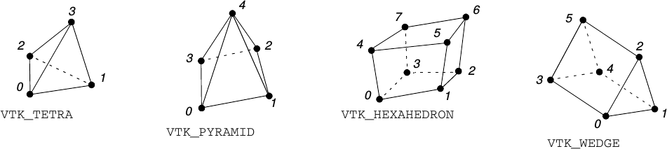
See 3D Grid format for format description.
-
hybmeshpack.hmscript.export3d_grid_vtk(gid, fname_grid=None, fname_surface=None)¶ Exports 3D grid and its surface to vtk ascii format.
Parameters: - gid – 3D grid file identifier or list of identifiers
- fname_grid (str-or-None) – filename for grid output.
- fname_surface (str-or-None) – filename for surface output.
Only hexahedron, prism, wedge and tetrahedron cells could be exported as a grid. Surface export takes arbitrary grid.
If a filename is None then respective export will be omitted.
Boundary types are exported as a field called
boundary_typesto surface output file.
-
hybmeshpack.hmscript.export3d_grid_gmsh(gid, fname)¶ Exports 3D grid to gmsh ascii format.
Parameters: - gid – grid identifier or list of identifiers
- fname (str) – output filename.
Only grids with tetrahedral/hexahedral/prism/pyramid cells could be exported.
Boundary edges will be exported as Elements of triangle/quadrangle type. All boundary types which present in grid will be exported as Physical Groups with an id identical to boundary index and respective Physical Name.
-
hybmeshpack.hmscript.export3d_grid_msh(gid, fname, periodic_pairs=[])¶ Exports 3D grid to fluent msh ascii format.
Parameters: - gid – 3D grid file identifier or list of identifiers
- grid (str) – filename for output
- periodic_pairs (list) –
[periodic-0, shadow-0, periodic-point-0, shadow-point-0,
periodic-1, shadow-1, periodic-point-1, ...]
Each periodic pair is defined by four values:
periodic- boundary identifier for periodic surfaceshadow- boundary identifier for shadow surfaceperiodic-point- point in [x, y, z] format on periodic contourshadow-point- point in [x, y, z] format on shadow contour
Given points will be projected to closest vertex on the boundaries of respective subsurfaces.
Periodic and shadow subsurfaces should be singly connected and topologically equivalent with respect to given points. For surface 2D topology definition periodic/shadow surfaces are taken with outside/inside normals respectively.
-
hybmeshpack.hmscript.export3d_grid_tecplot(gid, fname)¶ Exports 3D grid to tecplot ascii format.
Parameters: - gid – 3D grid file identifier or list of identifiers
- grid (str) – filename for output
A grid zone and zones for each boundary surface defined by boundary type will be created in the output file.
All 3D cells will be saved as FEPOLYHEDRON elements.
-
hybmeshpack.hmscript.export3d_surface_hmc(sid, fname, fmt='ascii')¶ Exports 3d surface to hybmesh native format.
Parameters: - sid – single or list of surface identifiers
- fname (str) – output filename
- fmt (str) –
output data format:
'ascii'- all fields will be saved as text fields,'bin'- all fields will be saved in binary section,'fbin'- only floating point fields will be saved in binary section.
See 3D Surface format for format description.
-
hybmeshpack.hmscript.export_all_hmd(fname, fmt='ascii')¶ Exports all geometrical data to native format.
Parameters: - fname (str) – output filename
- fmt (str) –
output data format:
'ascii'- all fields will be saved as text fields,'bin'- all fields will be saved in binary section,'fbin'- only floating point fields will be saved in binary section.
See Native File Formats for description.
-
hybmeshpack.hmscript.save_project(fname, fmt='ascii')¶ Saves current command flow and data to HybMesh project file.
Parameters: - fname (str) – file name
- fmt (str) –
output data format:
'ascii'- all fields will be saved as text fields,'bin'- all fields will be saved in binary section,'fbin'- only floating point fields will be saved in binary section.
See Project Workflow Format for description.
Import
-
hybmeshpack.hmscript.import_grid_hmg(fname, gridname='', allgrids=False)¶ Imports grid from native hmg file.
Parameters: - fname (str) – file name.
- gridname (str) – name of a grid to find in the file. If gridname is not specified then the first grid will be taken.
- allgrids (bool) – if True then all grids from the file will be imported.
Returns: grid identifier or list of identifiers if allgrids is set.
-
hybmeshpack.hmscript.import_grid_msh(fname)¶ Imports grid from fluent msh file.
Parameters: fname (str) – file name Returns: grid identifier
-
hybmeshpack.hmscript.import_grid_gmsh(fname)¶ Imports grid from gmsh ascii file.
Parameters: fname (str) – file name Returns: grid identifier Only triangle and quad elements are supported.
Boundary types could be exported by passing boundary edges as certain Elements of “Line” type. Their physical entity tag (first one amoung real tags) will be treated as their boundary index. For each such index the new boundary type will be registered in the program flow if it has not been registered yet. Name for the new boundary type will be taken from PhysicalNames field if it exists, otherwise the default name “gmsh-boundary-index” will be used.
-
hybmeshpack.hmscript.import_contour_hmc(fname, contname='', allconts=False)¶ Imports contour from hybmesh native format.
Parameters: - fname (str) – filename
- contname (str) – name of the contour to import. If contname is not specified then the first one will be taken.
- allconts (bool) – if True then all contours from the file will be imported. contname will be ignored.
Returns: contour identifier/list of identifiers if allconts is set.
-
hybmeshpack.hmscript.import3d_grid_hmg(fname, gridname='', allgrids=False)¶ Imports grid from native hmg file.
Parameters: - fname (str) – file name.
- gridname (str) – name of the grid to import. If not specified then the first grid will be loaded.
- allgrids (bool) – if True then all grids from the file will be imported.
Returns: grid identifier/list of identifiers if allgrids is set.
-
hybmeshpack.hmscript.import3d_surface_hmc(fname, srfname='', allsurfs=False)¶ Imports surface from hybmesh native format.
Parameters: - fname (str) – filename
- srfname (str) – name of the surface to import. If srfname is not specified then the first one will be taken.
- allsurfs (bool) – if True then all surfaces from the file will be imported. srfname will be ignored.
Returns: surface identifier or list of identifiers if allsurfs is set.
-
hybmeshpack.hmscript.import_all_hmd(fname)¶ Imports all geometry objects found in a file of native format.
Parameters: fname (str) – filename Returns: list of loaded objects as [[grid2d ids], [contour2d ids], [grid3d ids], [surface3d ids]]
-
hybmeshpack.hmscript.load_project(fname)¶ Loads command flow and data from HybMesh project file.
Parameters: fname (str) – file name All existing data will be lost.
See Project Workflow Format for description.
Introductory Examples
- Example 1 uses
exclude_contours(),unite_grids(),build_boundary_grid1(). - Example 2 uses
unite_grids(). Illustrates boundary features translation. - Example 3 uses
build_boundary_grid(). Complicated boundary grid building. - Example 4 uses
map_grid(),snap_grid_to_contour(). - Example 5 uses
extrude_grid(),export3d_grid_msh()with 3D periodic conditions. - Example 6 uses
partition_contour(),matched_partition(),stripe(),triangulate_domain(),pebi_fill(). Different approaches to non-regular domain meshing.