Native File Formats
Native hybmesh files are separated into two sections. The first section
is a xml document with a root element called <HybMeshData> with
possible attributes. The second section is a binary data.
It stores numeric array values only. If file has no binary data then
binary section is empty and the whole file is a valid xml document
which could be read by any xml parser.
Binary section starts directly after root xml element closing tag </HybMeshData>
without any intermediate whitespaces like \n, \r etc.
Indexing of all primitives in hybmesh data format starts from 0. Index equals -1 (for example in face-cell connectivity) shows absence of primitive (no cell connected to one of face sides, i.e. a boundary face).
File extension convention is:
- *.hmg files contain only set of 2D or 3D grids,
- *.hmc files contain set of contours and surfaces,
- *.hmd files contain set of all possible geometric data,
- *.hmp files contain hybmesh project files;
Numeric arrays storage
All geometric data is stored in numeric array xml elements
<NAME type="char/int/float/double" format="ascii/binary" dim="1/2/3/.../variable">
NAMEis a numeric array name which depends on what data it represents.typeattribute represents data type stored in array. Currently hybmesh generator supports four possible types:char,int,floatanddouble.formatattribute could equalasciiorbinary. It shows if data is stored in xml node as an ascii string or in a binary section.dimattribute shows vector dimension of data. It could equal"1","2","3", ... for one-, two-, three- (or any other positive integer) dimension vector. A special valuevariableprovides vectors which dimensions vary from one entry to another. In the latter case each entry dimension is written as an unsigned integer before entry values.
Array element doesn’t contain any information regarding total size of the array because it should be understood from
the context. type and format attributes are mandatory for each numeric array; dim value
in most cases is known from the context and this attribute could be omitted.
There are no restrictions on data type and format depending on the context.
Any data could be stored in any supported format. For example you could store points coordinates
with 'char' or face-cell connectivity table using 'float' type. It’d still be a
valid hybmesh format numeric array
(of course it would be automatically converted into doubles and integers respectively while loading into hybmesh).
Elements with format="ascii" storage contain its data string in a text field.
Numeric values in this string are separated using any amount of any whitespaces.
char values are represented as integers in [-127, 127] interval.
For binary data format="binary" numeric array elements contain a subnode called START which stores
a byte position in a binary section where data of this record starts.
char arrays use 1 byte per value; integer and float arrays – 4 bytes per value;
double arrays – 8 bytes per value.
For dim="variable" cases each number representing dimension of an entry is written using 4 bytes as an
unsigned integer.
All binary data is stored using little-endian format.
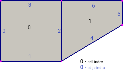
fig. 1
Lets say we want to write a numeric array representing cell-edge connectivity of a grid depicted in fig. 1. This array is not needed by 2d grid storage format. However it could be saved as a user defined field in a node representing cell structure. As we can see from the picture this would be an integer vector of two entries (one for each cell); each entry has a dimension of 4 as both cells are formed by four edges. So in ascii format it would be written as
<HybMeshData>
  .....
  <GRID2D>
    <CELLS>
      <FIELD name="__cell_edges__" type="int" format="ascii" dim="4">
        0 1 2 3
        4 5 6 2
      </FIELD>
      .....
    </CELLS>
    .....
  </GRID2D>
</HybMeshData>
We can also write this vector using variable vector format form:
<HybMeshData>
  .....
  <GRID2D>
    <CELLS>
      <FIELD name="__cell_edges__" type="int" format="ascii" dim="variable">
        4   0 1 2 3
        4   4 5 6 2
      </FIELD>
      .....
    </CELLS>
    .....
  </GRID2D>
</HybMeshData>
In binary format xml part of this record will look like
<HybMeshData>
  .....
  <GRID2D>
    <CELLS>
      <FIELD name="__cell_edges__" type="int" format="ascii" dim="4">
        <START>1111</START>
      </FIELD>
      .....
    </CELLS>
    .....
  </GRID2D>
</HybMeshData>
taking into account that first 1111 bytes of binary buffer are used by some other data. Total amount of bytes which are used by this array is
length of array(=2) * dimension(=4) * size of integer (=4) = 32and binary buffer by itself will be
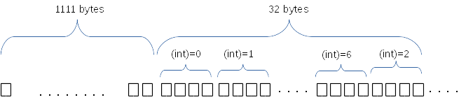
fig. 2
Using format="binary" dim="variable" the same data will be represented as
<HybMeshData>
  .....
  <GRID2D>
    <CELLS>
      <FIELD name="__cell_edges__" type="int" format="ascii" dim="variable">
        <START>1111</START>
      </FIELD>
      .....
    </CELLS>
    .....
  </GRID2D>
</HybMeshData>
Buffer length will be equal to
size of unsigned interger(=4) + dimension of the first entry(=4) * size of integer(=4) +size of unsigned interger(=4) + dimension of the second entry(=4) * size of integer(=4) = 40 bytesand look like
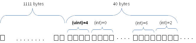
fig. 3
User defined fields
Along with mandatory geometric specific fields each set of geometric primitives
could be supplied with arbitrary number of user defined fields.
All of those fields are ignored by hybmesh reader
(except for fields called "__boundary_types__") but could be
useful for external solver readers.
Those fields are written into a hybmesh file as an ordinary numeric arrays called FIELD with one supplemented attribute name which defines the name of user defined field:
<FIELD name="field_name" type="char/int/float/double" format="ascii/binary" dim="1/2/3/.../variable">
If attribute dim is omitted then the array is treated as a scalar data with dim=1.
If grid or contour has non-zero boundary types, then a field
named "__boundary_type__" will be automatically added to elements representing
EDGES (for 2D data) or FACES (for 3D data) structure.
Hybmesh could also save grids providing some additional grid information which is stored in those fields. For example for 2D grids additional cell-vertices or cell-edges connectivity table could be calculated and saved into __cell_vertices__ and __cell_edges__ fields. Note that all of those fields created by HybMesh are conventionally dubbed using leading and ending double underscores. See specific grid export functions to see other possible data which could be written.
2D Grid Format
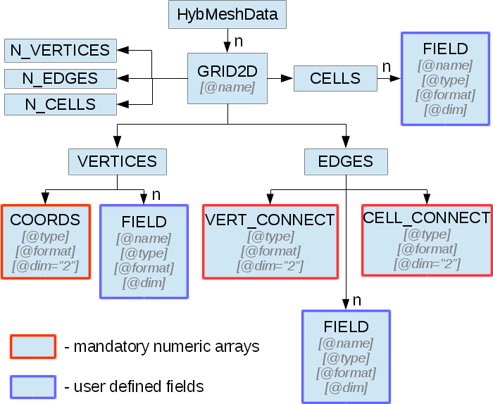
fig. 4
Structure of xml part of a file containing set of 2D grids is shown in figure 4. Each grid is stored in an element called GRID2D. It should have a name unique to all grids stored in the file. Elements N_VERTICES, N_EDGES, N_CELLS contain number of vertices, edges and cells of the grid respectively.
Element VERTICES stores grid vertex information. Its mandatory subnode COORDS stores coordinates of grid points as a numeric array. Vector dimension of this array is always 2 so “dim” attribute of the element should be omitted.
Element EDGES presents grid edges structure. In subnode VERT_CONNECT edge-vertex connectivity is stored as a numeric array of vector dimension of 2. For each edge it represents index of start vertex and index of end vertex in the edge.
Subnode CELL_CONNECT provides edge-cell connectivity. This is also a numeric array of integer values and vector dimension of 2. For each edge it stores indices of left and right adjacent cells. Direction of edge is defined by the order of vertices given in VERT_CONNECT table. So the right cell is located to the right hand side if one looks from the start vertex towards the end vertex. If this is a boundary edge and there is no right or left adjacent cell than -1 should be placed on its place.
EDGES node could also provide special user field named "__boundary_types__"
which will be interpreted by hybmesh as edges boundary types. Note that
user field for edges set should contain data for all edges including inner and boundary ones.
For inner edges a boundary type could be safely set to zero.
Element CELLS provides no valuable information on grid geometry since it was fully defined in VERTICES and EDGES elements and could by empty.
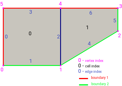
fig. 5
A grid depicted in figure 5 will be written to ascii hmg file as
<HybMeshData>
  <GRID2D name="Grid1">
    <N_VERTICES>6</N_VERTICES>
    <N_EDGES>7</N_EDGES>
    <N_CELLS>2</N_CELLS>
    <VERTICES>
      <COORDS type="double" format="ascii">
        0 0
        0.5 0
        1.0 0.3
        1.0 0.5
        0.5 0.5
        0 0.5
      </COORDS>
    </VERTICES>
    <EDGES>
      <VERT_CONNECT type="int" format="ascii">
        0 5
        0 1
        1 4
        4 5
        1 2
        2 3
        3 4
      </VERT_CONNECT>
      <CELL_CONNECT type="int" format="ascii">
        -1 0
        0 -1
        0 1
        0 -1
        1 -1
        1 -1
        1 -1
      </CELL_CONNECT>
      <FIELD name="__boundary_types__" type="char" format="ascii">
         1 2 0 1 2 2 1
      </FIELD>
    </EDGES>
    <CELLS/>
  </GRID2D>
</HybMeshData>
2D Contour Format
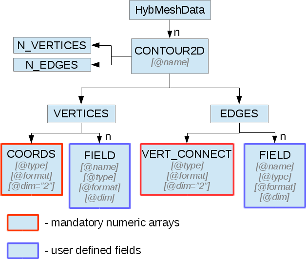
fig. 6
Hybmesh treats contours as a set of connected edges. There is no restriction on whether this connection provides closed or open contour or even a set of not connected edges. So this information is not stored in a file. Structure of xml part of a file containing set of 2d contour is shown in figure 6. Each contour is saved in an element called CONTOUR2D. It should have a name unique to all contours stored in the file. Elements N_VERTICES, N_EDGES contain number of vertices and edges of the contour respectively.
Element VERTICES stores contour vertices information. Its mandatory subnode COORDS contains coordinates of points as a numeric array. Vector dimension of this array is always 2 and “dim” attribute of the element should be omitted.
Element EDGES presents edges structure. Its only mandatory subnode VERT_CONNECT contains edge-vertex connectivity as a numeric array with vector dimension of 2. For each edge it represents index of start vertex and index of end vertex of the edge.
EDGES node could also provide special user field named __boundary_types__
which will be interpreted by hybmesh as edges boundary types.
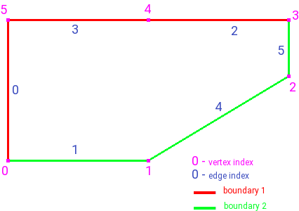
fig. 7
A contour depicted in figure 7 will be written to ascii hmc file as
<HybMeshData>
  <CONTOUR2D name="Contour1">
    <N_VERTICES>6</N_VERTICES>
    <N_EDGES>6</N_EDGES>
    <VERTICES>
      <COORDS type="double" format="ascii">
        0 0
        0.5 0
        1.0 0.3
        1.0 0.5
        0.5 0.5
        0 0.5
      </COORDS>
    </VERTICES>
    <EDGES>
      <VERT_CONNECT type="int" format="ascii">
        0 5
        0 1
        3 4
        4 5
        1 2
        2 3
      </VERT_CONNECT>
      <FIELD name="__boundary_types__" type="char" format="ascii">
        1 2 1 1 2 2
      </FIELD>
    </EDGES>
  </CONTOUR2D>
</HybMeshData>
3D Grid format
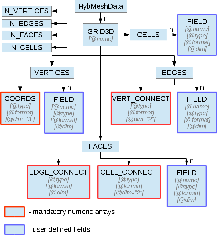
fig. 8
Structure of xml part of a file containing set of 3d grids is shown in figure 8. Each grid is stored in an element called GRID3D. It should have a name unique to all grids stored in the file. Elements N_VERTICES, N_EDGES, N_FACES, N_CELLS contain number of vertices, edges, faces and cells of the grid respectively.
Element VERTICES stores grid vertex information. Its mandatory subnode COORDS stores coordinates of grid points as a numeric array. Vector dimension of this array is always 3 so “dim” attribute of the element should be omitted.
Element EDGES presents grid edges structure. In subnode VERT_CONNECT edge-vertex connectivity is stored as a numeric array of vector dimension of 2. For each edge it represents index of start vertex and index of end vertex in the edge.
Element FACES presents grid faces structure. In subnode EDGE_CONNECT edge-vertex connectivity is stored as a numeric array of vector. Its dimension could be fixed or variable depending on type of the grid. For each face it represents ordered indices of edges which form the face.
Subnode CELL_CONNECT provides face-cell connectivity. This is a numeric array of integer values with vector dimension of 2. For each face it stores indices of left and right adjacent cells. Direction of faces is defined by the order of edges given in EDGE_CONNECT table. If one looks at the face and sees its edges in counterclockwise ordering than he looks from its right towards its left side. If this is a boundary face and there is no right or left adjacent cell than -1 should be placed on its place.
FACES node could also provide special user field named __boundary_types__
which will be interpreted by hybmesh as a boundary features of faces.
Element CELLS provides no valuable information on grid geometry since it was fully defined in previously defined elements and could by empty.
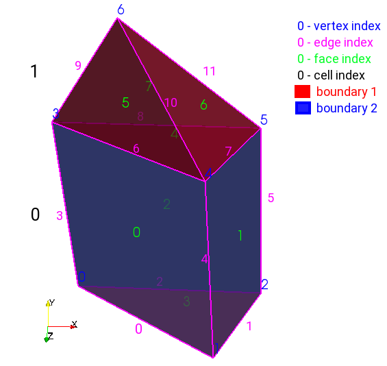
fig. 9
A grid depicted in figure 9 will be written to ascii hmg file as
<HybMeshData>
  <GRID3D name="Grid1">
    <N_VERTICES>7</N_VERTICES>
    <N_EDGES>12</N_EDGES>
    <N_FACES>8</N_FACES>
    <N_CELLS>2</N_CELLS>
    <VERTICES>
      <COORDS type="double" format="ascii">
        0 0 0
        0.8 0 0.5
        1 0 0
        0 1 0
        0.8 1 0.5
        1 1 0
        0.5 1.7 0.5
      </COORDS>
    </VERTICES>
    <EDGES>
      <VERT_CONNECT type="int" format="ascii">
        0 1
        1 2
        0 2
        0 3
        1 4
        2 5
        3 4
        4 5
        3 5
        3 6
        4 6
        5 6
      </VERT_CONNECT>
    </EDGES>
    <FACES>
      <EDGE_CONNECT type="int" format="ascii" dim="variable">
        4   0 4 6 3
        4   1 5 7 4
        4   2 5 8 3
        3   0 1 2
        3   6 7 8
        3   6 10 9
        3   7 11 10
        3   9 8 11
      </EDGE_CONNECT>
      <CELL_CONNECT type="int" format="ascii">
        0 -1
        0 -1
        -1 0
        -1 0
        0 1
        1 -1
        1 -1
        -1 1
      </CELL_CONNECT>
      <FIELD name="__boundary_types__" type="char" format="ascii">
        2 2 2 1 0 1 1 1
      </FIELD>
    </FACES>
    <CELLS/>
  </GRID2D>
</HybMeshData>
3D Surface format
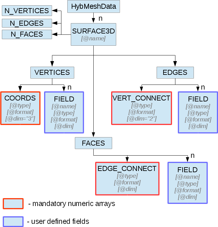
fig. 10
Hybmesh treats surfaces as a set of connected faces. There is no restriction on whether this connection provides closed or open surface or even a set of not connected faces. So this information is not stored in a file. Structure of xml part of a file containing set of surfaces is shown in figure 8. Each surface is stored in an element called SURFACE3D. It should have a name unique to all surfaces stored in the file. Elements N_VERTICES, N_EDGES, N_FACES contain number of vertices, edges and faces of the surface respectively.
Element VERTICES stores surface vertex information. Its mandatory subnode COORDS contains coordinates of grid points as a numeric array. Vector dimension of this array is always 3 so “dim” attribute of the element should be omitted.
Element EDGES presents grid edges structure. In subnode VERT_CONNECT edge-vertex connectivity is stored as a numeric array of vector dimension of 2. For each edge it represents index of start vertex and index of end vertex in the edge.
Element FACES presents surface faces structure. In subnode EDGE_CONNECT edge-vertex connectivity is stored as a numeric array of vectors. Its dimension could be fixed or variable depending on type of the surface. For each face it represents ordered indices of edges which form the face.
FACES node could also provide special user field named __boundary_types__
which will be interpreted by hybmesh as a boundary features of faces.
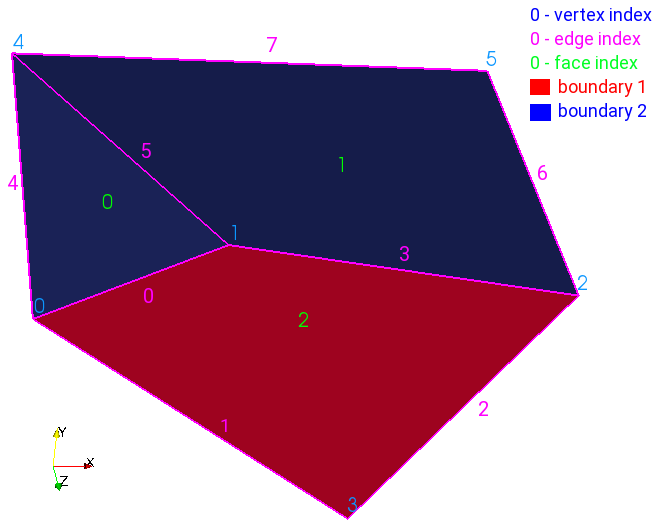
fig. 11
A surface depicted in figure 11 will be written to ascii hmc file as
<HybMeshData>
  <SURFACE3D name="Surface1">
    <N_VERTICES>6</N_VERTICES>
    <N_EDGES>8</N_EDGES>
    <N_FACES>3</N_FACES>
    <VERTICES>
      <COORDS type="double" format="ascii">
        0 0 0
        0.7 0 -0.5
        2 0.1 0
        1 0 1
        0 1 0
        1.5 1 0
      </COORDS>
    </VERTICES>
    <EDGES>
      <VERT_CONNECT type="int" format="ascii">
        0 1
        0 3
        2 3
        1 2
        0 4
        1 4
        2 5
        4 5
      </VERT_CONNECT>
    </EDGES>
    <FACES>
      <EDGE_CONNECT type="int" format="ascii" dim="variable">
        3   0 5 4
        4   3 6 7 5
        4   0 1 2 3
      </EDGE_CONNECT>
      <FIELD name="__boundary_types__" type="char" format="ascii">
        2 2 1
      </FIELD>
    </FACES>
  </SURFACE3D>
</HybMeshData>
Project Workflow Format
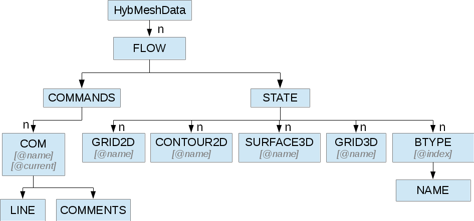
fig. 12
A file representing hybmesh project contains sequence of all commands and current state of the program including all current geometrical objects
Its xml structure is depicted in figure 12. Each workflow is stored in FLOW nodes. One project file could possibly contain multiple work flows with its own set of data and commands. Command sequence for a flow is stored in element called COMMANDS. Each command is represented by xml element
<COM name="command name">
  <LINE>command options</LINE>
  <COMMENS>some user comments</COMMENTS>
</COM>
where command name is an internal hybmesh name of the command and command options is a internal string representation of command options. One of the command (most likely the very last one) should be supplied with attribute current=”1”. This shows hybmesh that the state of the program is saved at the moment after execution of this command.
The program state is written in element called STATE. It contains all 2d grids, 3d grids, 2d contours, and surfaces present in the current program state. Nodes BTYPE store registered boundary types: their integer index and user defined name.